
My Rx7 S8 Track Car Build
Announcements
-
Similar Content
-
-
Latest Posts
-
 Seems like a decent result for a modded JZX110. They are bulky in comparison to the 100 and 90 models (which I'd prefer myself) but they are getting very few and far between here in JP these days. Thanks for the detailed review and the import process into the UK. I also have a car which I'm hoping to export from Japan at some stage so it's good to know if someone from the UK was interested in it. By the way the corrosion underneath is par for the course for cars which were located in/near the mountains or along the Japan sea coastline. They get huge amounts of snow every winter and the sodium chloride is used on the roads. Many cars have some kind of rubber like treatment underneath but they tend to limit it to the wheel arches underbody and fuel tank. Suspension arms and sub-frames will have similar corrosion to your JZX110 which is a common sight. See it all the time and car dealers here generally don't even mention it unless asked.
 -
 If the sound goes away when you clutch in, the 1.5/2 way diffs are just shit, and you are a normal person. The diff is likely "fine" but driving at anything under 30kmh is a violent horrible experience. It would be exaggerated with solid diff bushings and subframe bushings if you have those.
 -
 Trailer got new mudguards to accommodate the new wheels Lightweight ally Painted, stickered and done ✅ 👌
 -
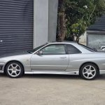
 Did you hit up the search function? R33 and greddy and cable returns this thread with some options. https://www.sau.com.au/forums/topic/358214-rb25-throttle-body/
 -
 Thanks buddy.. the standard one needs to be about another inch or inch and a half longer. Thanks anyway
-


Recommended Posts
Create an account or sign in to comment
You need to be a member in order to leave a comment
Create an account
Sign up for a new account in our community. It's easy!
Register a new accountSign in
Already have an account? Sign in here.
Sign In Now