Jump to content
SAU Community

Recommended Posts

Specs of the new setup:

  • Head reconditioned
  • Camtech 272 cams (VCT removed)
  • Custom spring/retainer setup
  • ARP head studs
  • Nitto headgasket
  • Garret GTW3476 turbo with custom twin scroll 0.82 rear housing
  • 6boost manifold
  • Turbosmart 40mm external wastegates (x2)
  • RB26 plenum
  • Adaptronic M6000 Modular ECU
  • 2200cc injectors
  • Fuel rail
  • Extra fuel pump in surge tank
  • Like 1

Enter Aus Time Attack. Day of frustration.

First of all, get to the track the morning of the event (car had been unloaded in to the garage the day before) and the car won't start. After some dicking about thinking it was due to the cold temps with E85 and lack of cold start tune on the car, we noticed the fuel pumps weren't even priming. After some testing and chasing wires through the car, we found that the old alarm/immobiliser had failed and wasn't provided a power signal to the pump relays. Ripped that out....aaand that was half the day gone.

Get out on track, car is feeling good. Come back in from a couple of laps to check things over and find that the insulation on the bonnet had sagged and caught fire :7_sweat_smile:. Luckily had only just done so. Ripped that out, no damage, good to go.

Next session, head out, come in for my first hot lap, get through the kink and turn 2, lose all throttle. Car still running but no throttle. Stop car. Open bonnet, throttle cable had come loose, no biggy. Oh, except for the litre of oil that is all over my engine bay..... /facepalm.

Get back to the garage thinking the worse, turns out the catch can had just filled and overflowed. Phew..spend the next half hour cleaning the car up. All looks good. Start car, oil starts leaking. Turns out the oil drain hose had split. Annoying. By the time I get in to town to get a new hose and fit it up, all my sessions had finished. Luckily for me Boz is such a nice guy he let me run in the Open class group as there was only a couple of cars running by this point, which allowed me to get some seat time in the car. After not driving the car for 6+ months I had lost my finess no doubt, but was glad to see the car was running ok at this point.

End Aus Time Attack day.

Moving on, I got some better hose for the oil return line and replaced this. Now time for a local supersprint at Mount Panorama.

19243135_1590323620987619_85197038086497

Things went much better this time around with the only issue being a melted boost line which was easily replaced. I placed 1st in class and second outright with a new PB of 48.52 seconds. In-car footage of my fastest run here below:

19511278_1591501644203150_42543765243933

19420688_1591501637536484_83265233548613

  • Like 2

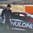
After this I installed a fresh set of Intima Type D pads in the front calipers before attending Nulon Nationals Round 3 at SMSP with the BLCC team.

20017868_1614618551891459_36134451922139

Unfortunately I battled with wiring gremlins and heat issues the majority of the day. Time to start sorting out this factory loom (which I would soon find had melted lol).

20121516_1618878618132119_45870610867804

  • Like 1

Whilst attacking the wiring I decided it was time to spend the money on braided lines all around the hot side. Clearly heat wasn't going to be nice. Insert big box of Aeroflow parts here haha >>>

20507497_1633394113347236_36984576203150

With this I made up a braided oil drain hose for the turbo as well as installed a Turbosmart OPR for the turbo. All boost lines to the wastegates were also replaced with braided line. Apparently I don't have a photo of any of this installed so will have to get around to that lol.

I tidied up the wiring loom near the turbo which was a complete mess. I also removed the ABS unit and installed a heat shield next the turbo/exhaust. To help with getting heat out of the engine bay I also tracked down a Ztune style bonnet and fitted that.

It was also decided to rewire the fuel pumps with new relays and clean up the wiring for them to assist in any diagnosis in the future after the Aus Time Attack events.

  • Like 5
3 hours ago, blah_blah said:

ah damn was hoping to see a seperate boost graph from start. when does it make full boost?


Whats the main difference between the GTW and GTX turbos?

Yea unfortunately that's all I have. Was a late night of tuning so didn't think to change the graph up.

Honestly not entirely sure on the differences between GTW and GTX, I went with Matt's recommendation on the turbo and after seeing the same turbo on big yella (Nulon's SR20 Civic) and Matt's shop car running the GTW3884 I was impressed by the results so went with it. Best decision I've made with the car. The old turbo didn't hit full boost (17psi) until 4200rpm. As you can see  this setup is around 24psi at 4000rpm, big difference. I'm making the same power as before at about 4900rpm with better response lol, but a lot has changed to make that happen.

  • Like 1
2 minutes ago, iruvyouskyrine said:

Did you change the sump when doing everything? Noticed in the video from bathurst you are getting your oil pressure light come on under braking :)

Nope, stock sump remains..... why?

3a5.jpg

But in all seriousness, yes I have noticed the light comes on briefly. Plan was to get an ASR sump in there before WTAC but money has eluded me due to some unexpected costs outside of the garage. During my test day at SMSP the oil pressure looked good, but as soon as funds allow sump will be changed and possibly will go down the route of an Accusump or something like that. As it stands, the bottom end of the engine is COMPLETELY stock lol.

Chuck them up when you do. I asked otaku garage multiple times would this be a problem and was told no every time. Then ofcourse when I purchased and went to fit it was not even close to fitting.

This is a cool car, I saw it at Redsun actually :)

That plenum adapter is a shame, I asked Matt about it after seeing it installed on your car and he showed me a number of photos which look identical to the ones above. It's possible but no way is it as "bolt-on" as Otaku Garage claim..

From seeing how it was made to work in person I can confidently say there's no way they actually bolted an RB26 plenum to an RB25 head with this adapter.

Create an account or sign in to comment

You need to be a member in order to leave a comment

Create an account

Sign up for a new account in our community. It's easy!

Register a new account

Sign in

Already have an account? Sign in here.

Sign In Now


  • Similar Content

  • Latest Posts

    • For once a good news  It needed to be adjusted by that one nut and it is ok  At least something was easy But thank you very much for help. But a small issue is now(gearbox) that when the car is stationary you can hear "clinking" from gearbox so some of the bearing is 100% not that happy... It goes away once you push clutch so it is 100% gearbox. Just if you know...what that bearing could be? It sounding like "spun bearing" but it is louder.
    • Yeah, that's fine**. But the numbers you came up with are just wrong. Try it for yourself. Put in any voltage from the possible range and see what result you get. You get nonsense. ** When I say "fine", I mean, it's still shit. The very simple linear formula (slope & intercept) is shit for a sensor with a non-linear response. This is the curve, from your data above. Look at the CURVE! It's only really linear between about 30 and 90 °C. And if you used only that range to define a curve, it would be great. But you would go more and more wrong as you went to higher temps. And that is why the slope & intercept found when you use 50 and 150 as the end points is so bad halfway between those points. The real curve is a long way below the linear curve which just zips straight between the end points, like this one. You could probably use the same slope and a lower intercept, to move that straight line down, and spread the error out. But you would 5-10°C off in a lot of places. You'd need to say what temperature range you really wanted to be most right - say, 100 to 130, and plop the line closest to teh real curve in that region, which would make it quite wrong down at the lower temperatures. Let me just say that HPTuners are not being realistic in only allowing for a simple linear curve. 
    • I feel I should re-iterate. The above picture is the only option available in the software and the blurb from HP Tuners I quoted earlier is the only way to add data to it and that's the description they offer as to how to figure it out. The only fields available is the blank box after (Input/ ) and the box right before = Output. Those are the only numbers that can be entered.
    • No, your formula is arse backwards. Mine is totally different to yours, and is the one I said was bang on at 50 and 150. I'll put your data into Excel (actually it already is, chart it and fit a linear fit to it, aiming to make it evenly wrong across the whole span. But not now. Other things to do first.
    • God damnit. The only option I actually have in the software is the one that is screenshotted. I am glad that I at least got it right... for those two points. Would it actually change anything if I chose/used 80C and 120C as the two points instead? My brain wants to imagine the formula put into HPtuners would be the same equation, otherwise none of this makes sense to me, unless: 1) The formula you put into VCM Scanner/HPTuners is always linear 2) The two points/input pairs are only arbitrary to choose (as the documentation implies) IF the actual scaling of the sensor is linear. then 3) If the scaling is not linear, the two points you choose matter a great deal, because the formula will draw a line between those two points only.
×
×
  • Create New...