Jump to content
SAU Community

Recommended Posts

The SAU forums are definitely a great resource on our cars, thanks to you guys. :thumbsup:

I've had the AFM fail on me once before, on the highway no less. The engine simply cranked out and wouldn't fire up again. I was under the impression the stock turbo had munched itself, and consequently the engine, but the guys at APC here in Brisbane correctly diagnosed it and fitted a new AFM at a good price.

This time round though, I think the reason for the engine misbehaving might have to do with the fact that there's a VQ35DE + stock M35 turbo lurking under the hood. Sorry, I should probably have mentioned that earlier.

The Meisters are from IM. They stick out a fair bit, so the fenders are in the process of getting pulled. I'm hoping the very slight variance in front and rear offsets won't upset the ATTESA system...

Small difference in offset should be OK. Was anything done about the ecu when the +T was done? e.g. ecu from turbo car? If not what are you planning - some kind of pigyback unit?

This time round though, I think the reason for the engine misbehaving might have to do with the fact that there's a VQ35DE + stock M35 turbo lurking under the hood. Sorry, I should probably have mentioned that earlier.

and when abouts had you planned on elaborating about this!

Glad to hear the offsets should be fine, thanks!

It's running on the stock M35 ECU atm, apparently the A/F ratios were spot on.

Been advised I'll need a Motec M800 to get the whole show going since the stock ECU won't play nice with the 35's variable valve timing.

I was driving around everywhere in gears 4 and 5 (Tiptronic), luckily the engine is tractable enough. Other than that there's not much to report, but if you have any q's just ask away biggrin.gif

Pic's please.....VQ35..........got to see it!

oh....and!!!!

Injectors and E-manage in....only the tune to go tomorrow!

Edited by Jetwreck

This thread is useless without PICS! :stupid::) :)

Are you running the HR? I don't think there's much difference between my non HR hydraulic actuators and the coil actuated retarders on the VQ25det. They are both two wire coils you just need a way of changing the pulse to them.

You need at least some kind of management, how are you adjusting fuel? Emanage would probably do it but you really need standalone management like m800, ps2000, then the dramas will really start. :whistling:

Is the engine built? Fill us all in pleeaaasse. :yes:

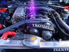
I didn't bother taking engine bay pics. It looks almost stock. The only visual differences are some new piping, airbox out and pod filter in, and the intake manifold inlet pipe swapped sides (was on the left before, now it's on the right).

Might take pics if I get half a chance tomorrow.

The engine is internally stock. Is it true the VQ35DE has forged conrods and crank?

I think they are glass not forged. :)

How did you come across this setup? A stock VQ25 turbo is not a good idea on a 3.5L high compression high reving engine period. Imo it is most certainly a downgrade from the VQ25det unless you built it with forged pistons, H beam rods, lower compression and a much larger turbo.

A pic would tell me all I need to know about the engine model.

Just put my new R32 RDA slotted front disks and A1RM's in, now to bed them in. :devil:

you should bed the pads in on the old rotors i believe (or could be the other way round)

there is a thing about it in the diy/tutorial section

I didn't bother taking engine bay pics. It looks almost stock. The only visual differences are some new piping, airbox out and pod filter in, and the intake manifold inlet pipe swapped sides (was on the left before, now it's on the right).

Might take pics if I get half a chance tomorrow.

The engine is internally stock. Is it true the VQ35DE has forged conrods and crank?

Mate....it's a pretty be claim....you would be the first to have a VQ35 in an NM35 in OZ......hence the reason you must post photo's(how hard is it to your phone out and take a shot??

btw......did you say the standard ECU is running it ATM? I can not see how that would work as although the 25 and 35 are from the same family they are still different in a couple of way's that would make me think that more than likely would not work!....e.g. How is the timing controlled at all?...different system's. And why the M800......Haltech PS2000 would be more than good enough at a quarter of the price.

Also you would have had to have the motor nearly apart to change the sump so why would you not have done new rod's and pistons so that it can handle more than 7 to 8psi without throwing a rod out the side one day? Unless of cause it's 2WD now? Or is the motor out of a PM35?

Anyway.....I need you to post up some more info/photo's on this as I am NOT believing you atm!

P.S. I await your photo's and comments so that you can flame mewhistling.gif

Edited by Jetwreck

you should bed the pads in on the old rotors i believe (or could be the other way round)

there is a thing about it in the diy/tutorial section

Yeah, use the old pads to bed the new discs, then throw the new pads in and bed them.

Edited by Daleo

Yeah, use the old pads to bed the new discs, then throw the new pads in and bed them.

too late....his on the way over to see me atm!

I told him just get up to 50-60km's and apply a firm and static brake peddle....the redo about 5 - 10 time's....should be OK then! The guy that sold the bakes said the same thing!

too late....his on the way over to see me atm!

I told him just get up to 50-60km's and apply a firm and static brake peddle....the redo about 5 - 10 time's....should be OK then! The guy that sold the bakes said the same thing!

Meh, don't matter, I've bedded new pads on new discs a bunch of times, never had any issues :whistling:

^^ I knew this too but at the time I changed all my pads and rotors there was no way I was in the mood to do it a second time to change pads later on!!

As for this vq35DE.....T?? I would love to see pics too you can't keep us on edge like this we need a fix!!!

Create an account or sign in to comment

You need to be a member in order to leave a comment

Create an account

Sign up for a new account in our community. It's easy!

Register a new account

Sign in

Already have an account? Sign in here.

Sign In Now


  • Similar Content

  • Latest Posts

    • Yeah, that's fine**. But the numbers you came up with are just wrong. Try it for yourself. Put in any voltage from the possible range and see what result you get. You get nonsense. ** When I say "fine", I mean, it's still shit. The very simple linear formula (slope & intercept) is shit for a sensor with a non-linear response. This is the curve, from your data above. Look at the CURVE! It's only really linear between about 30 and 90 °C. And if you used only that range to define a curve, it would be great. But you would go more and more wrong as you went to higher temps. And that is why the slope & intercept found when you use 50 and 150 as the end points is so bad halfway between those points. The real curve is a long way below the linear curve which just zips straight between the end points, like this one. You could probably use the same slope and a lower intercept, to move that straight line down, and spread the error out. But you would 5-10°C off in a lot of places. You'd need to say what temperature range you really wanted to be most right - say, 100 to 130, and plop the line closest to teh real curve in that region, which would make it quite wrong down at the lower temperatures. Let me just say that HPTuners are not being realistic in only allowing for a simple linear curve. 
    • I feel I should re-iterate. The above picture is the only option available in the software and the blurb from HP Tuners I quoted earlier is the only way to add data to it and that's the description they offer as to how to figure it out. The only fields available is the blank box after (Input/ ) and the box right before = Output. Those are the only numbers that can be entered.
    • No, your formula is arse backwards. Mine is totally different to yours, and is the one I said was bang on at 50 and 150. I'll put your data into Excel (actually it already is, chart it and fit a linear fit to it, aiming to make it evenly wrong across the whole span. But not now. Other things to do first.
    • God damnit. The only option I actually have in the software is the one that is screenshotted. I am glad that I at least got it right... for those two points. Would it actually change anything if I chose/used 80C and 120C as the two points instead? My brain wants to imagine the formula put into HPtuners would be the same equation, otherwise none of this makes sense to me, unless: 1) The formula you put into VCM Scanner/HPTuners is always linear 2) The two points/input pairs are only arbitrary to choose (as the documentation implies) IF the actual scaling of the sensor is linear. then 3) If the scaling is not linear, the two points you choose matter a great deal, because the formula will draw a line between those two points only.
    • Nah, that is hella wrong. If I do a simple linear between 150°C (0.407v) and 50°C (2.98v) I get the formula Temperature = -38.8651*voltage + 165.8181 It is perfectly correct at 50 and 150, but it is as much as 20° out in the region of 110°C, because the actual data is significantly non-linear there. It is no more than 4° out down at the lowest temperatures, but is is seriously shit almost everywhere. I cannot believe that the instruction is to do a 2 point linear fit. I would say the method I used previously would have to be better.
×
×
  • Create New...