Search the Community
Showing results for tags 'nissan'.
-

Squeaking clutch/throw out bearing
patrickxdf12 posted a topic in R Series (R30, R31, R32, R33, R34)
Hello! i just finished manual swaping my r34 skyline with a r33 rb20de box(RB71C)box When the car is running it squeaks crazy loud and it was smoking from the gearbox area. The gearbox is fine it was tested. The clutch slave cylinder seems like it doesn't fully releases the clutch. I want to ask if this noise is from the throw out bearing or could it be the clutch assembly or disk att.xFliq87Gzw6kImKBVqDebXkj0fBqymk0JaYeP3_3SlM.mp4 -
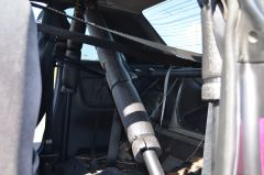
 Alrighty guys so this guide/ build log/ r&d will outline how i installed the entire cruise control system from an a32 nissan maxima into my 2000 wgnc34 nissan stagea rsfours type b. So firstly I’ll just state I am just a 19 year old who has absolutely no qualifications, just an interest in electronics and car audio with, in the big scheme of things, not much experience at all. Take all of this information as just a guide and your own r&d as who knows, some of the things may even be considered dangerous! I do welcome feedback and questions though! Prerequisites and Warnings; If you can’t understand how to read, interpret and follow a proper Nissan wiring diagram I’d advise you not to attempt. You must be competent with a soldering iron and or crimping connections If you don’t know how to use all the functions of a standard multimeter do not attempt at all You will have to modify the clock spring, which houses the airbag wiring. This is a large risk that can result in airbag deployment if completed incorrectly then there is the obvious risk of fire/short circuit if any electrical connections are incorrect or poorly terminated etc/not fused i will not be wasting time showing you how to take your interior apart. if you cant workout how to remove your steering wheel/speedo cluster etc you probably dont have the ability to install cruise control into your stagea. Step 1 Wiring diagrams; The wiring greatly differs between automatic and manual vehicles, with the latter being far more simple as transmission control is not needed. It is probably possible with autos but I have not investigated if the transmission control systems share commonalities. I have included both so you can see the differences. Manual transmission Automatic transmission This series of diagrams --cruise control wiring diagram.pdf-- are the in depth wiring diagrams showing all factory pinouts, wire colours etc. they are just what a proper wiring diagrams are. within these diagrams there are various notes such as this one-- what i did was print out the full diagram and white out any unnecessary automatic parts of the diagram to simplify it. i also suggest taking note in this document ---how to read wiring diagrams.pdf---on how to properly read these wiring diagrams and most importantly for pinouts, understanding if a pinout is shown from terminal side or harness side. Step 2: What you will need A32 nissan maxima parts ascd control unit vacuum motor vacuum cable actuator ascd clutch switch ascd brake switch (looks the same as clutch switch, just take both switches on the brake pedal bracket and the clutch switch) ascd steering wheel switch ascd hold relay ascd main switch (can get a usdm d21 pathfinder switch i believe if you want the writing on it to be correct and not horizontal) note: cut off everything with any plugs etc included and give yourself as much loom behind it as possible (atleast 100mm or so), take all bolts/fasteners too take the clock spring and all the wiring inside the steering wheel becuase it comes in handy if you want to incorporate a dash light that says "cruise" take the maxima cluster and connectors too stagea parts you will need a steering wheel that has the large D shape side airbag bolt covers with brackets housed inside. i think series 1 wheels are like this but im not sure what models come like this. all i know is my rs4s wheel is smaller and doesnt have provisions for any audio control (left side) or cruise control (right side). second photo shows said bracket the throttle with second wheel bit (think this came on most autos but again not sure) parts you can get from any car the longest fattest section of wiring loom you can extract from a car (you could go try and find all the colours in maxima wiring diagrams, but i just used what i had and spliced the colours i had in between the maxima terminated ends. consumables and tools 6m of 7 or so mm split loom a heap of double wall heatshrink of assorted sizes electrical tape thats decent your usual pliers,flush cutters, crimping pliers, wire strippers solder and soldering iron pin removal tool and afew of them in different styles the most dangerous tool in the shop (stanley knife.utility knife) t50 torx socket t40 torx socket 17mm socket 10mm socket but seriously does anyone have any of these? phillips head screwdriver and tiny flatheads etc parrot clip leads for your multimeter (the spring loaded clamp ones that allow you to lock onto wires/pins) Step 3: modification (guess you could say fabrication) in this step il be showing you how i (poorly) mounted the ascd vacuum pump, actuator, modified the clock spring, modified the ascd controller case and modified the brake pedal. Clock spring the stock clock spring in my s2 rs4s type b has 3 wires in stock form, (steering wheel side) brown (batt12+), blue and yellow (airbag) The connector on the steering column side of the clock spring had 7 male pins as shown in this photo, (ignore the pen markings) so that got me thinking, if there is a 7 pin input to the ribbon cable there must be a way to add 4 more wires to the steering wheel side. see 7 copper pins through clear window in clock spring. i then peeled the sticker on the face back to reveal the clip that secures the steering wheel wires of the clock spring. to remove this cover the two plastic pins that appear quite butchered in the picture below (top and bottom) need to be cut down with a utility knife as they are melted down larger than the id of the covers holes to ensure if the two centre clips fail there is no chance the cover can come off. they need to be cut down so the "od" of the centre squashed pins are smaller than the "id" of the cover holes as shown in the picture. once the plastic "pins"were modified and free, the centre clip needs to be squashed together releasing the cover. the next picture shows the connection of steering wheel wires to the clock spring copper with cover removed (stock rs4s type b). you would probably find a tiptronic series 2 clock spring has 2 wires you could use for cruise control which means you may not have to perform these modifications. thats just a guess though, and i choose modifying my own over sourcing one to find out if thats the case. next, i cut the connector off the maxima clock spring show in picture below to add to the stagea clock spring. i removed these pins from the maxima connector with a custom pin removal tool that is inserted into the front and the plastic tabs were lifted up, releasing the pins out the back. the wires were then pushed through the stagea wire black sheath shown in picture below and roughly bent to where they would be soldered. (top 3 blue yellow green wires) i then realised there would be a spare pin available so i pushed a blue/orange wire through the airbag black sheath for any future use i think of. the wires insulation were then stripped about 4mm or so, and all were soldered onto the copper pads. (see blue/orange wire second from right). only 2 wires are needed for cruise control out of the 4 that i added total, but i happened to have the opportunity to buy a rare factory option steering wheel audio controller and knew this would require one additional wire, and planned to use that final blue/orange wire in some sort of a scramble high boost mode button configuration on the wheel, hence using all 4 wires. Important soldering tip: pre tin your wires and pre tin the pads. DO NOT put excessive heat into the copper pads at any time. this will melt the delicate ribbon connector attached to the other side ruining the clock spring for good. i did one at a time quickly (tinning helps this) allowing the copper to completely cool between wires. the base of the wires were then secured to the plastic with a small amount of 2 part epoxy. i then pushed the three pins (blue green yellow) into the stagea black connector with the brown wire (horn batt12v+) and there the blue orange wire is loose coming from the airbag connector wire sheath. i then checked continuity between steering wheel pins and rear of clock spring pins and ensured there were no shorts between wires, especially the airbag pins! once i new the modifications were successful, the wire cover was put back on. some material needed to be shaved off the inside to allow more room for the 4 extra wires. once it clipped into place with the centre clip, i used the soldering iron to slightly melt the plastic "pins" ensuring it would never come off, slightly similar to how it was secured from factory. thats it clock spring done! ascd vacuum pump and actuator All i did was mount the pump to the same bracket i had my catch can on in the back passenger side of the engine bay, and made a shitty bracket out of some steel and aluminium that i had lying around to mount the vacuum cable actuator to. this actuator is on the drivers side rear of the bay. im sure far more elegant nice mounts can be made up it works for me haha. ascd controller case (mounting) i mounted the ascd controller behind the drivers side kick panel on the relay bracket. first thing i did was remove one half of the ascd controllers case by bending out the pressed metal around it. once removed the outer metal case, i drilled out the 4 spot welds without going all the way through, removing the factory bracket. i then wire wheeled both the case and relay mount bracket and soldered the 2 together. the case was then put back together and edges bent back to secure it. the photo below shows the final product once completed. brake pedal in my rs4s there was only one weld in nut/captive nut whatever you call it on the brake pedal bracket for the stock brake switch. there is a second hold there but no weld in nut. there is also only one contact for the brake switch and no second one at all. for from my limited research i believe all autos come with both weld in nuts and both contacts ready to go (no modification necessary) (photo below shows view from behind with welded nut, contact and second hole with no nut) to modify; step 1 crack a bleed nipple on a calliper with a clear vinyl tube over it going up to a reservoir/drink bottle or something to collect brake fluid. this is necessary because you need to be able to push the pedal to the floor. step 2: push down pedal with your elbow or whatever and attempt to pry out that little rubber contact you can see in photo above. step 3: get yourself a bolt and nut ( i used a 16mm long m8 high tensile bolt and nut) and steel plate step 4: put bolt through steel plate (if the plate is less than 2mm thick you wont need to grind down bolt head) and push pedal down and put bolt through the hole where the rubber contact previously was and put nut on the back. align plate with the hole where the second brake switch will go and tighten nut and bolt with pedal pressed down.(first pic is side view showing bolt-2X1mm plate-pedal-nut) step 5: this step will make you want to give up. if you finish this you can finish the whole install. you will need a mate with a broom stick or some sort of long pokey device to push the pedal down while your upside down in the footwell. get the stock brake switch and a second nut in hand. get your friend to push the pedal down to the floor and get up in there and put the brake switch through the hole and try and thread the nut back onto the switch from behind. you will now have 2 nuts on the switch clamping it to the bracket. do not tighten down yet. step 6: adjust brake switch back and fourth, with your friend pushing pedal in when necessary, with both nuts so you achieve around 0-0.8mm gap between the switch housing and the contact. to see this you will need to get a phone camera up in there or something. step 5 and 6 definitely are the most difficult, curse inducing, hatred building, case of beer break worthy aspects of the whole cruise control install. step 7: put the brake interrupt switch in and adjust so there is 0-0.8mm of gap between the switch housing and the contact (now the bolt head) see photo below brake switch modifications complete! see photo below for photo Step 4: The wiring So you should have gathered a heap of body loom or wires of different colours from a wrecker/parts car already. ideally you want to use the same colour as the diagram but as long as you record what colours you use etc you should be fine. il tackle this section in the same way i did in mine, one page of the wiring diagram at a time. i will often refer to "running pin so and so to a given location" and in virtually all circumstances out of the car this wire run was a 1.5m or so extended length i had soldered in the colour i chose to the nissan maxima plug if that makes sense. where possible to simplify wire routing i grouped as many as i could in the one run of split loom and when i new i would have afew wires going to the same location i used a drill to for twisted pairs or a larger twisted loom. i ran 3 main "runs" of split loom, one to the main switch, one to the clock spring and any brake switches and a third into the engine bay for the ascd vacuum pump. i suggest soldering extended lengths of wire for all "runs" to the plugs/pins you will add such as brake switches, clock spring connector etc, then running these wires through split loom so they all end up at the ascd controller area and final soldering is consolidated to one location after all other connections are finished. Page 1 of wiring diagram (EL-145 main switch) and page 5 of wiring diagram (el-149)/ "run 1" of split loom so this page for the manual transmission diagram only has just the main switch wiring and ascd hold relay. first wire: pin 1 of the ascd main switch. this is ign power and it is the same source as the ign power for the ascd hold relay. what i did is i found luckily in my scrap wiring loom, a pin that is the same as the pins on the interior fuse panel connector. i chose to do this as factory as possible so i pulled out the fuse panel, bridged the ign relay and traced out 10A fuse that isnt used with the continuity function and found the ign output pin for this fuse. the first photo shows that bottom row, 3 from left (white out indicator) pin will give you 12v+ ign through the red fuse in photo 2 with the white out on it (bottom row 2 from far left) to add the female pin to the harness side connector i sourced the same pin out of the scrap loom i had which looks like the photo below. according to the wiring diagram this wire runs to the main switch (which goes rhs of steering wheel next to fog light switch in speedo cluster surround) and also the ascd main switch (mounted on the ascd controller relay bracket) so i ran the wire off the pin back down the loom towards the mass of wires inside the upper part of kick panel (as a sub loom) then, as i earlier spliced a second wire into the long length (made a y split), i ran one side down to where the ascd relay mounts and one forward out the dash where the ascd switch goes. just incase your connector falls apart like mine did (dont fully take out the inner pin securing backing plastic on connector, i learnt the hard way) here is the wire colours and placement on the connector. the pink/blue wire is the pin i added that connects to third from left as referred to before and the fuse. now pin 4 and 6 of the main switch are both just grounds (pin 6 shows it goes to el-ill or the speedo cluster but upon further investigation its just a ground). i soldered pin 4 wire to pin 6 wire 100mm or so down from the connector and then ran the ground wire right down to where the ascd relay is (same run as the 12v ign+ pin 1 wire). pin 2 and 3 wires were ran down to where the ascd relay is and pin 5 wire was ran 150mm or so down the run of wires then came out of the loom as it were to go to the speedo cluster. now page 5 (el-149) shows pin 7 (speed sensor) and pin 13 (cruise lamp indicator) both go to the combination metre (speedo cluster) so i ran these lengths of wire up the same split loom as the ascd main switch wires, and had them come out in the same spot as the pin 5 of the switch to form a sub loom that heads towards the cluster. (photo below shows 3 speedo sub loom wires before i moved them 150mm down the loom for neater routing. a thicker gauge ground wire with ring terminal crimped and soldered to the end is then thread up "run 1" from the ascd relay area up to where the "Y" is that goes off in the sub loom to the fuse panel connector. this ring terminal is bolted to the common ground thats really obvious just above the large opening in the kick panel metal. pin 2 of the ascd hold relay is crimped and soldered with the ground (pin 4 of the ascd main switch), and pin 3 of the ascd controller to the other end of the thicker ground (down at the ascd relay to form one large common ground for everything. so this "run 1" loom, from ascd main switch to ascd hold relay/ascd controller" has all 6 wires from the switch, a ground and the ign 12v+ fuse panel wire thats splits off in the middle , then 3 split off to the speedo (pin 7 of controller speed sensor, pin 13 of controller cruise lamp, and pin 5 of the main switch the illumination). Page 1 (EL-145),2 (EL-146),3 (EL-147) or "Run 2" of split loom this will be split into 2 sections, brake switch interrupts and clock spring connector. all wires in this section run down the same loom Brake switches so following on from the first section or "run 1" of loom, pin 2 of the ascd main switch on diagram EL-145 when you simplify it, ties into pin 3 of the ascd hold relay, pin 4 of the ascd controller and also then goes off to pin 1 of the ascd clutch switch. what i did here is i connected all 4 wires together in one location down where the ascd hold relay/ascd controller is. the photo below shows run 1 coming in and hidden under heatshrink and tape this 4 way junction takes place and the green/black wire thats visible is now going off in run 2 towards the clutch switch. also in "run 2" a length of wire is ran from the ascd controller area to the brake switch area to connect to pin 5 of the controller and pin 2 of the brake switch. another run of wire is ran from the ascd controller area to the brake switch area through "run 2" split loom to connect to pin 11 of the ascd controller and splice into the factory brake pedal pin 1 (this is the stop lamp switch, sends +12v to the ascd controller when pressed like your brake light) thats it for the brake switch part. will continue the next sections in more comments as this is way too long for poor old sau and its lagging heavily (probably my crappy late 2011 macbook pro)
 -
 If the page links doesn't work, please manually enter the page number into URL for the corresponding page. This post was updated on: 01/06/2017: This thread is here providing information on our high flowed or built turbos as well as installation and trouble shooting. I'm happy to help or assist with every one who is currently using or looking to purchase our products or services. Brief Introduction about our selves: We are Australian based turbocharger manufacture in Melbourne, We worked with experienced and skilled local engineers to produce our goods and we've been doing that since Oct 2007. We constantly update our production turbochargers and will do our best deliver value to our customers. My name is Stao you can PM or contact 0413457185 if any assistance is required. For our High flowed RB25 Turbos, they comes in 21U or OP6 from factory. The 21U rear housings are smaller can capable of 430HP after high flowing, and larger OP6 are capable of doing around 460HP. PU high flow option is available for any one chasing for 450 to 500HP. They are built with a larger .82 internally gated turbine housing with Nissan OEM bolton pattern, braided oil feeding line and a high pressure actuator. Below is the Rb25det Hitach turbo high flow catalog with few dyno sheets. ATR43SS is a OEM replacement powered up turbocharger built for RB20/25DET R32, R33 and R34 GTST and Stegea models. They are T3x based with OEM dump pipe pattern. This series is specifically engineered for speed with smooth street driving ability. ATR43 is a OEM replacement powered up turbocharger built for RB20/25DET R32, R33 and R34 GTST and Stegea models. They are T3x based comes in .63 and .82 turbine housing with OEM dump pipe pattern. Power is rated from 450HP to 600HP depends on profile chosen. Initial release date: 24/08/2009: We also carry out turbocharger repairs, housing/CHRA modifications and high flow services for All Garrett, HKS, Mitsubishi, Toyota, KKK and Made in China turbochargers. Do feel free to PM / contact us for free assistance. Check (if you live in usa): Costco Weekly Ad, or Supercheap Auto Catalogue. Important Installation Notes for RB2xdet Highflowed and PU units: Sleeve bearing turbochargers requires higher volume of oil flow, are sold with 50cm long braided oil feeding line line that replaces the standard oil restrictor in side factory oil lines, 12mm benjo bolt, and a M12x1.25mm speed flow adaptor. The adaptor goes onto the engine block, benjo bolts goes into the bearing housing with hollow screw supplied. 3x copper washers are required during installation, Which we can supply them for $9 additional or can be purchased at local auto stores. Factory water lines: T3x bearing housing used are 3mms shorter then OEM Hitachi's bearing housings. Means water lines needs to be very slightly bent / forced backwards. Stock actuator: We normally modify the factory actuator's fitting bracket allowing it for a bit of preloading. The actuator bracket bolt wholes has to be filed 5mms towards the turbine housing if not received with the turbo or getting fitted by others. Once done it can be adjust and pre-load ensuring the waste gate is 100% shut. For PU high flowed and ATR43 units with larger Diameter turbine housings, the engine side water line needs to be slightly bent / altered around the housing area. Installing ATR43 turbocharger: ATR43 units generally runs on a round 3inches inlet and round 2 inches out let. It is highly recommended to run a metal intake pipe. How ever if you wish to bolton to stock gears you need: 1x 3inch straight hose, 1x 2.5inch metal sleeve, 1x 2inches 90 degrees hose, 1x 2inches metal sleeve. We can supply all those parts for $100 extra. Tip for a easy installation would be removing the actuator with bracket pre-installation, that would allow lot more room for your tools to reach the manifold studs, and install the actuator and bracket back on after the rest of the installation is complete. Make sure the actuator is preloaded by roughly 3mms. Since larger turbine housings are used, due to larger physical size most of them would be taller then stock pushing the exhaust back by roughly 15mms. Most cars would be running an aftermarket exhausts, depending on the angle of the pre-made dump / front pipe, check the clearance between that to the Air-con water drain pipe. If fouls, simply by pulling it back with zip ties and secure it on the chassis. ATR43Gx/SS2 DIY with photos ATR43SS1xx DIY with photos and video Easy Induction pipes: http://www.sau.com.au/forums/topic/261613-hypergear-hiflow-service-continued/page-78 http://www.sau.com.au/forums/topic/261613-hypergear-hiflow-service-continued/page-89 Couple of extremely important factors: 1. After turbo installation do check pressure leaks ( I can make you a simple plug with a hose nipple for $50). Turbo will not perform if there are leaks. 2. Most of our turbos are installed with a 18psi high pressure actuator. by pass all boost controlling devices on test run, Boost gain from EBC based on stock actuator will cause massive boost creep. 3. Make sure the car's got a at least 3inch metal induction pipe with pod filter. Do not run those metal stuffed stock intake pipe. 4. An good exhaust system should restrict no more then 10KWs (My HKS silent power made 3KWs restrictions on a 316rwkws application). So Dyno tune with cat and exhaust dropped, (front pipe only). Do a touch up run with exhaust on after tuning, Get a better exhaust if you see a massive power drop with exhaust. If above procedures are followed you will definitely get the desired power goal. Also people with RB25det R33s. pay attention to those 20 years old valve springs and valves. Mine were all chewed out and worped possibly from valve float. That will act as boost leak, causing lose in power and response. Recommend stronger valve springs. Order, dispatch and mechanic services: All turbochargers are specifically built to suit customer's orders. We need in average 3 to 5 working days to have the order complete. We normally send with Australian post registered post with insurance, which generally takes 3 working days for delivery. We have 2x clients workshops in Melbourne which can carry out the installation service for $200, or onsite service for $250. For tuning, I personally use and recommend Status, and Dr.drift. ECU: For R33 RB25det I've personally used Adaptronic Plugin ECU and highly recommend it. The RRP price on this mode is $1499, We offer $400 discount of total if it is purchased with any of our turbochargers or high flow / rebuild service. Discount also apply for any customers whom is currently owning one of our built or high flowed turbochargers. Please check ECU features, results and discussion in page 113~116.
 -
 Hello all, I don't see any PDF online of this service manual being in OCR, so I'm posting a link of one I made. OCR makes it so much easier to find things, being able to search the document with Adobe Reader. (old link removed). new link - https://drive.google.com/file/d/0B495mmNsnU6uYzAwLV9fVW9WREk/view?resourcekey=0-Qa9Lfekqc5AnkoecCkM5xg It's 489 pages long.
 -
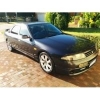
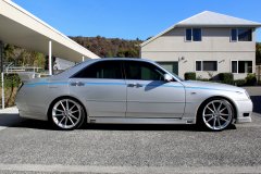
I will not respond to, "Is it still available?" I am the first Australian owner of this magnificent car. I have always serviced this 3.5 litre V6 with Mobil 1 Full Synthetic Oil. New Battery and wipers. Good Falken tyres, It has Cold Dual Zone A/C to keep you cool in summer & a Toasty Heater to keep you cozy in winter. Auxiliary DRL/Indicators to make yourself seen & Dash Mat. It has Multiple Airbags to keep you & your family safe, ABS, Traction & Stability control to keep you out of trouble. Smart key to get you in quick, Side & Rear Cameras to make parking a breeze. This silky smooth car has been a pleasure to own & drive. Averages 8.7 - 9l/100 km. Selling as I have upgraded. Message me for more info. If it's listed here, it's available.
-
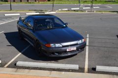
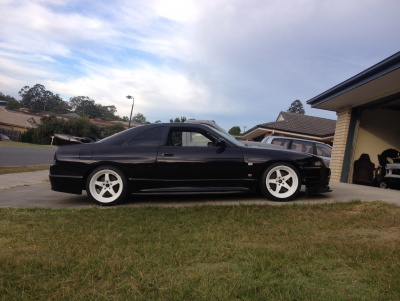
From the album: My R32 GTS-T
-
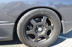
From the album: My R32 GTS-T
-
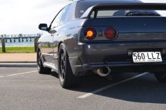
From the album: My R32 GTS-T
-
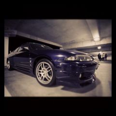
From the album: My R32 GTS-T
-
From the album: My R32 GTS-T
-
 Used OEM S1 front bar and S1 front lip for BCNR33 (62022-24U10, 96015-24U10) $1750 Bar and lip are damaged and therefore price is negotiable, so offer away! Brand new through Nissan's heritage program, expect to pay well over $2,500 for a new bar and lip. Damage is as follows: - holes from canards - heavy scrape on right side of lip - medium scrape on left side of lip - medium impact on right side (close to intercooler, check photos) - mesh coming off Damage is repairable! Would still be cheaper to fix and paint this one over buying a brand new one from Nissan! Bar is currently painted in K23 silver. Will NOT come with all mounting hardware (nuts and bolts)! No indicators! Pick up Casey area!
 -
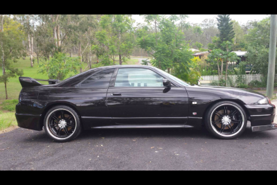
From the album: FOR SALE - 1996 R33 GTR
-
From the album: Arctopus album
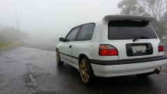
On our way back we stopped to admire the view, or lack there of... -
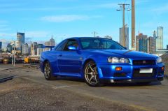
From the album: Arctopus album
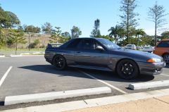
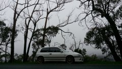
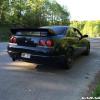
The first weekend after buying my R I took her into the hills. With nobody on the road and poor visibility it made for an unforgettable drive. -
From the album: Meet Gloria
-
- 1
-

-
- nissan gloria y34
- y34
- (and 2 more)
-
From the album: fluffy
Show us your car port !! -

From the album: Skyline R33 Gtst
-
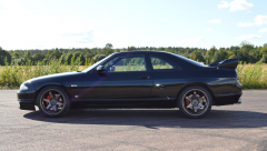
From the album: Skyline R33 Gtst
-
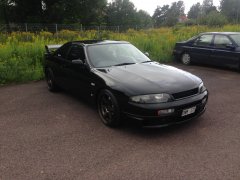
From the album: Skyline R33 Gtst
-

From the album: Skyline Nationals 2016
-
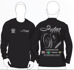
From the album: Skyline Nationals 2016
-
.thumb.JPG.cf2120a7648a369e8c7c30f420c0479a.JPG) C35 Laurel Centre Console Shroud Reproduced based on the Kids Heart Japan manual centre console There were only 200 made in Japan Made from high quality thick fibreglass. Comes with handbrake & gearstick sock clips. (pre fitted) Original Kids Heart pieces go for $1200-$2000 NZD If your lucky to find one $400 NZD Shipping on top depending where abouts! Shipping is $44 in NZ -------------------------------------------------------------------------------------------------------------------------------------------------------------------- C35 Laurel End Caps Made from high quality thick fibreglass. Comes with fitment brackets OEM plastic ones are $1000 NZD+ $500 Shipping on top depending where abouts! Shipping is $44 within NZ
C35 Laurel Centre Console Shroud Reproduced based on the Kids Heart Japan manual centre console There were only 200 made in Japan Made from high quality thick fibreglass. Comes with handbrake & gearstick sock clips. (pre fitted) Original Kids Heart pieces go for $1200-$2000 NZD If your lucky to find one $400 NZD Shipping on top depending where abouts! Shipping is $44 in NZ -------------------------------------------------------------------------------------------------------------------------------------------------------------------- C35 Laurel End Caps Made from high quality thick fibreglass. Comes with fitment brackets OEM plastic ones are $1000 NZD+ $500 Shipping on top depending where abouts! Shipping is $44 within NZ -
From the album: GTR33 V-SPEC - R33 GTS-t
-
From the album: GTR33 V-SPEC - R33 GTS-t
-
From the album: R34 GTR


.thumb.JPG.cf2120a7648a369e8c7c30f420c0479a.JPG)